System Verilog : Which final is Final ?

Dear Reader,

Recently I posted one blog post “System Verilog Final Means Final !”

As we all know final means final in system Verilog, Final block will get called at the end of the simulation before $finish. Now with this understanding we can have few questions. Recently I have received an request and some question on the same like and thought of answering those questions.
  1. Is multiple final block is allowed in System Verilog?
  2. If yes, what will be the execution order in simulation, which final is final?
Here are the answers to these questions :

Multiple final blocks are allowed in system Verilog, you can define multiple final block in your testbench. Some time you might require to use final blocks in different places of environment. Here we need to understand one most important thing on final block is that, final blocks are called at the end of the simulation before $finish. It is like a calling a function which executes in zero simulation time.

If you have multiple final block in your testbench all final blocks are called at same simulation time before your simulation ends. Let’s take an example to have better understanding:

program ankit_with_ankit;

  class final_test;
     task final_activity();
        $display (“ASIC With Ankit 1 @%t”,$time);
         #10;
       $display (“ASIC With Ankit 2 @%t”,$time);
     endtask
  endclass

  initial begin
     final_test ft;
     ft = new;
     ft.final_activity();
  end

  final begin
     $display (“ASIC With Ankit 3 @%t”,$time);
  end

  final begin
     $display (“ASIC With Ankit 4 @%t”,$time);
  end

endprogram

Simulation Result:

ASIC With Ankit 1 @ 0
ASIC With Ankit 2 @ 10
ASIC With Ankit 3 @ 10
ASIC With Ankit 4 @ 10

Here you can observe that I have used 2 final blocks in this simple exercises. You can have less or more based on your testbench requirement. When you run this with any simulator result will tell you all the final blocks will be called at same simulation time. So you could see all the messages for final blocks will be print at same simulation time. This is the reason you could see printing time for all the messages defined in the final blocks are 10ns.

So answer to question ‘which final is final?’ is ‘All finals are final’!

I hope this will give you a more understanding on final block usage and execution. Comments, suggestions are welcome. This blog post was published in the EDA Cafe .

Happy Reading!
ASIC With Ankit

System Verilog : Final means Final !

Dear Readers,

Today I would like to share some basic things on ‘final’ block in System Verilog. This is a newly added feature in System Verilog over Verilog. Final block is good for summary information. You can have summary information printed in log file at the end of simulation.

Final block executes at the end of the simulations without delays. ‘final’ block is like an initial block in SV only difference is that it occurs at the end of the simulations. Final block does not allow delays and time consuming or blocking activities and because of this reason it typically used in display statistical information on simulation result. Final block executes in zero time. Considering this nature of execution it is similar to ‘function’.Function also executes in zero time and does not allow timing related or blocking type of activities.

Lets try to understand this with syntax:

program asic_with_ankit;
   int error, warning;

    initial begin

      //Main program activities…..
    end
 
   final begin
      $display (“Test is done with %d errors and %d warnings”, error, warning);
    end
endprogram

Simulation ends means what?

Simulation ends when last initial block ends in the program. When last initial block ends, it implicitly calls $exit which tells particular program is done! When every program is completed (exited) an implicit call to $finish is done. User can call $finish any time whenever he/she wants to end the simulation.

This process does not mean that your simulation is over, a module or program can have one or more ‘final’blocks that contains code to be run just before simulator terminates/finishes.

This is a great place to perform certain activity in your simulation like:
  • Cleaning up tasks such as closing files
  • Printing reports which can have summary of number of warnings, errors etc..
  • Display statistic information about the simulation
final block can only trigger once in a simulations and because of this I name it as ‘final means final! :) you cannot call it again!

Happy Reading,
ASIC With Ankit

Is Test bench complex and difficult to handle at end of the day?

Dear Readers,

As we all know debugging is not an easy task and requires lots of attentions and effort to figure out the issues! Well, it is not at free of cost! (Debugging is not free!) This is true for both Design as well as Verification engineers.

ASIC/FPGAs are becoming more and more complex day by day and because of that RTL design and Verification environments are becoming super complex! Usually engineers start writing a code with good understanding in mind from defined specification or standards. With the complexity and sometime way of writing code makes design code / verification environment complex and difficult to handle. When debugging comes in picture, sometime discussion makes debugging easy. Thinking of possible scenarios, causes and problem solving ideas varies engineers to engineers! When you stuck with debugging some issue and you don’t get any clue, don’t spend huge amount of time debugging the same issue because “debugging is not free”, instead try discussing the scenario with your team mates, you would mostly get the hint or clue to identify and fix the issues. Obviously your colleague should be supportive in nature :). This is one of the potential places where TEAM work comes in picture!

Why the verification or design code becomes complex to handle at end of the day? What could be potential reason for this?
  1. Written code for Design/Verification itself is complex (because of thousands of functionalities, sometime because of way of writing)
  2. Engineers who have developed the design/verification environment start from scratch and leave the organization (Potential reason for now a day). In this case engineers leave with their all learning, concepts, tricks, algorithms and actual flow!
  3. When you don’t prepare architecture specification (top level as well as micro level). In this case you have to always rely on people who have been working on from years! This creates a solid dependencies for company, if those person leave because of any reason, it becomes very tough to maintain the design and verification environment for somebody who is new.
Customers always in hurry and wants their product ready and bug free! Critical situation comes when customer comes with their problem or with some new requirement support in design and you don’t have experienced person who have worked on this product. In this case engineers might face sleepless nights and will have to put lots and lots of efforts (because, they are not well aware of the design) to fulfill the requirement. Same requirements would have been fulfill with less amount of effort and as per expectation from client if engineers who have worked on this product are working!!
How could we avoid this type of pains?
  1. By making a habit of writing architectural documents with details. There could be different types of documents like top level architectural spec (which is useful for presentation), Micro level architectural documents (useful for engineers who are currently working and who will work in future as reference). Same is applicable for verification engineers for the architecture of verification environments.
  2. By not creating dependencies at certain level on any engineers and making sure that engineers keeps documenting changes/implementation done by them.
  3. By scheduling presentation/discussion on architecture and flow understanding for TEAM so that engineers working on the same product/protocol will gets understanding on flow.
  4. By following the standard verification methodology to reduce the pain of handing environment at certain extend since most of the methodology are user friendly and have many controls to handle complex environments.
Same blog post has been published on EDACafe blog portal, to access the same click here.
Happy Reading,

ASIC-FPGA Design Verification: Running Short of Business or Resource?

Dear Readers,

As we all know the semiconductor market looks good now days and lots of companies are hiring talents for 2013-14 projection. If we keep this projection in mind, we could say there would be a business for the companies for upcoming years. Now, the billion dollar question: ‘how about the resources’?

We have been observing from last few months that companies are struggling in finding good experienced/skilled resources. Usually product/service companies are playing with smart approach of having hierarchical engineering model where there are few junior/college graduates engineers working under guidance of one senior/Lead engineer. Approach looks smart and efficient to utilize resources appropriately and makes engineering execution cost effective too! At the same time executive and managers always thinks on cost effective and efficient engineering model to fulfill dynamic time to market! Many companies are working with different approach to utilize and manage engineering resources efficiently.

There are cases or project specific critical requirements where you don’t have time to train your junior resources, in this type of requirement; you cannot take a chance of using junior level resource, if you do so, you might lose the schedule, budget and at the end market which is very important! There could be a requirement where you don’t need all your skilled resources to work on. For this type of requirement you can create a hierarchical approach of your engineering model to use the skillset efficiently. (This is where the engineering management comes in picture, Managers; Executives have to take efficient decisions to move forward in this type of situation otherwise in long go, you could see impact on quality and customer)

Now a day, most requirements and needs from the product based companies are for senior engineers, considering the critical project requirement and quick execution to make the products ahead in the market. Companies are feeling shortage of skilled resources. At the same time people don’t move easily! Question here is; Does this create shortage of experienced skillsets?

When market is in good shape, revenue and financial graph is growing mostly all the companies are in need of skilled man power and that’s where competition comes in picture for companies and engineers too! There can be different type of situations where market is not in good shape and companies are struggling to get the business. In these types of situation Smart companies usually starts investing in engineering man power to develop the skillsets keeping projection in mind, by the time skilled requirement comes, company already have skilled/trained resources ready to jump in to!

There can be other type of situation where market might or might not be in good shape. Irrespective of market Situations Company sometime announces on ‘restructuring the engineering force’ which means company directly or indirectly fires engineers as a part re-structuring. Mostly this situation comes because of shortage of business for company (particular business division of company).

These types of situations are still debatable and require dynamic changes based on the market, need, requirements etc… But still the question remains same at any point of time ‘Are Companies Running Short Of Business or Short Of Resource?’

Same blog post has been published on EETimes blog portal:

You can read same blog post on EETIndia, click here !

Thanks,
ASIC With Ankit

The two Door Keepers: An Assertion, to make sure bad thing does not happen and coverage, to make sure Good thing happens!

Dear Readers,

The two Door Keepers: An Assertion, to make sure bad thing does not happen and coverage, to make sure Good thing happens!
 
As we all know SVA (System Verilog Assertions) and SV Coverage are playing major role in test bench implementation which helps us achieving maximum confidence on bug free design. These components in the test environments are working as a ‘Door Keepers’! Assertions are mainly doing job to make sure bad things does not happen and Coverage is mainly doing job to make sure Good thing happens!!
 

Assertions are usually connected to the DUT (Design Under Test) through interface and keeps continuous eye on activities per clock. This way it is making sure that nothing bad happens, if so, it will inform user that something went wrong on particular clock.  Simulation tools are also intelligent in different ways (through log dump, GUI dump etc…) to report assertion failures! In SVA there are two types of Assertions, 1.  Immediate and 2. Concurrent Assertion. (For more details on assertions please see blog on ‘coverage model in system verilog’)


Functional Coverage are connected with different entities in the test bench to captures the information from the various places of test bench. Coverage gives us an enough confidence to make sure Good thing happens during the simulation. Functionality of functional coverage is to make sure that functional items, scenarios or stimulus are generated and covered. Functional coverage gives us confidence more on test bench whether all the identified, defined coverage items are generated and covered or not! At some extend functional coverage also makes sure that nothing bad has generated during the simulation. To catch such kind of unexpected behavior we have illegal and ignore bins!! As we know simulation tools are intelligent enough to catch expected and unexpected behavior and dump that in to .ucdb (coverage) files.
Assertions and Coverage are doing such a great job in test simulation and making sure nothing bad happens and also makes sure Good simulations happens! These Door Keepers are giving heads up at the end of the simulation if something went wrong during the simulation.
As a conclusion, we should not see assertion message at the end of the simulation message and should see lots of coverage information in successful simulation!
We, the engineers have to always make sure that ‘Door Keepers’ are intelligent and efficient!!
Happy Reading! Enjoy!

Most of the re-spins are due to Functional defects?

Dear Readers,
I have been hearing on re-spins of chips. Many companies have gone through this painful phase because of several reason/defects. Nobody likes re-spin for chip as it is expensive and time consuming! Companies have a fear to loose time to market for their products because of this reason.
Let us understand the various factors which could cause re-spin for chips. If you ask industry experts or Semiconductor veterans they could share their experience. I have been discussing this topic with couple of people and have concluded few factors which could cause re-spin.
  1. Firmware Issues
  2. Power Issues
  3. Mixed-Signal Interface related Issues
  4. Race Condition Issues
  5. Clocking domain Issues
  6. Functional Issue etc...
From the experience and discussion it looks like most of the time Function Issues/defects have triggered a re-spin for the Chips. When we talk about functional issues, attention comes to our mind is for functional logic verification part. Considering complexities in the ASICs companies have started investing time and money for the functional verification part of the Chips to reduce the chances of re-spin.
To reduce the chances of re-spin for chips, people have started using various precautions like
-        A reusable and scalable verification
-        More effective block (IP) level verification
-        Verification reuse from block level to System level
-        Architecture of test bench using reusable methodologies
-        Constraint Random Verification approach (Refer: Blog post on Constraint Random Verification)
Random functional verification is giving us a enough confidence on functional defects. Random verification generates corner scenarios, stress testing on functional scenarios and logical permutation for configuration.
 
Random verification just gives us a confidence on functional defects but not giving us confirmation that Chip will not have to go through re-spin because of any of the functional issue.
 
Share your experience on Chip re-spin.
 
Happy Reading-Sharing,

System Verilog : Ignoring function's return value!

Dear Readers,

functions and tasks are the very useful features in Verilog/System Verilog. We have been using these features since long in our test  bench development.

Though 'function' is available in verilog as well as in System Verilog, there is difference! Now you may want to know what is that difference.

Let me first explain you the differences between task and functions for Verilog language :


  1. Tasks can consume time while a function can not which means
  • tasks can have delays #50 while functions can not have.
  • tasks can also have blocking statements such as @(posedge clock) or wait (xyz) while functions can not have.
  • tasks can call functions while reverse case is not allowed (function can not call task)
Now let us understand what is the difference between usage of function in verilog and system verilog?

Verilog must return a value and a value must be used but In System Verilog If you want to call a function and ignore its return value, you can cast the result to void.

Conclusion :

If you have System Verilog task that does not uses or consume time, we should make it a void function. If you do this, you are free to use this this functions from any task or functions. This is the reason people are using debugging routine as void function rather than a task so that it can be called from any task or function:

For Example:

function void print_value (...........);
   $display ("Value of A=%h B=%h C=%h", $time);
endfunction

Here we can see the syntax of usage, $display is not a time consuming feature and at the same time we don't have any other time consuming statements as discussed earlier like delays, blocking statement... This type of function does not need return value to be used. This will ignores returns value.

Hope this is a useful post to understand basic difference between functions and tasks in System Verilog.

Keep Reading & Sharing,
ASIC With Ankit

System Verilog : Functional Coverage Options features

Dear Readers,

Functional Coverage is very important in Test Bench Design. It gives us a confidence on covered items listed on verification plan/items. Usually the goal of verification engineer is to ensure that the design behaves correctly in its real environment.

Defining coverage model is very important for any test bench to get the enough confidence on design verification. You can read more on 'Coverage Model in System Verilog'

Here I would like to share some of the important feature of System Verilog Functional Coverage which helps engineer during verification activity.

Coverage Options available in System Verilog through which you can specify additional information in the cover group using provided options

1. Cover Group Comment - 'option.comment'
You can add a comment in to coverage report to make them easier while analysing:

covergroup CoverComment ;
  option.comment = "Register Definition section 1.1";
  coverpoint reg;
endgroup

In example, you could see the usage of 'option.comment' feature. This way you can make the coverage group easier for the analysis.

2. Per Instance Coverage - 'option.per_instance'
In your test bench, you might have instantiated coverage group multiple times. By default System Verilog collects all the coverage data from all the instances. You might have more than one generator and they might generate different streams of transaction. In this case you may want to see separate reports. Using this option you can keep track of coverage for each instance.

covergroup CoverPerInstance ;
  coverpoint tr.byte_cnt;
  option.per_instance = 1;
endgroup

3. Threshold using - 'option.at_least' 
This feature is useful when you don't have sufficient visibility in to the design to gather robust coverage. There might be the cases where you just have an information of number of cycles that are needed for the transfers to cover required errors to get generated/simulated for defined cover point. Here you could set the option.at_leaset. For example if we know that we need 10 cycles to cover this particular cover point, you could define option.at_leaset = 10.

4. Control on Empty bins - option.cross_num_print_missing = 1000
System verilog coverage report by default shows only the bins with samples. But usually as a verification engineer our job is to verify all cover point that are listed in verification plan.

covergroup CoverCrossNumPrintMissing ;
    ByteCnt : coverpoint tr.byte_cnt;
    Length : coverpoint tr.length;
   option.cross_num_print_missing = 1000;
endgroup

5. Coverage Goal - option.goal
In system verilog, coverage goal for a cover group or point is the level at which the group or point is considered fully covered.

covergroup CoverGoal ;
    coverpoint tr.length;
    option.goal = 80;
endgroup

These are the few important coverage option features which are very useful in defining/coding System Verilog Functional Coverage.

Keep Reading,
ASIC With Ankit

Technology Product Services : "Putting Eggs On More Baskets"

Dear Readers,

We could see many semiconductor product technology services companies have been launched in last few years. Recently I read one article on EE Times India which says "Indian Startup Stats: 379 tech startups launched; 87 closed" This article describes that Indian entrepreneurs are moving ahead with their technology and business experience. Most of the companies are able to make the success in Product Services, Pure Services, Product Development in the field of Technology Products.

I was discussing these with some of the experienced and successful person in the Technology field and concluded that "Putting Eggs on more Bakets" is the safe and Smart way to get succeed and to make the sustainable business. There are many painful things when somebody is starting a company in technology product service field, like Raising an initial Fund, Quick Revenue flow, To get consumers for business etc. These are the common challenges for any new comers in the business field but analysis says that many Indian companies are able to manage these initial pains and proved themselves and came out from this phase.

Once the company comes out from initial pain and revenue starts flowing with the business expansion, second challenge for company is to improve and maintain the business review flow to make the better place in the business field. Experience and study shows that most of the company follows 'Putting Eggs on more Basket' strategy for better stability for long term future.

Putting Eggs on more Basket means expanding customer base or dealing with more customer. In this type of Business Model, In case if one of your customer failed in their business and you lost them, you wont be in serious trouble (definitely there will be impact on business but mostly those are manageable with quick management decision) because you have eggs (service business) on more Baskets (customers). So you wont be completely stuck or in trouble, your revenue flow will not get completely stopped and you can spend your effort to expand your customer base with the help of your ongoing revenue flow and mostly you can be back on track quickly. Most of the services company works on this type of business model for better stability

Ultimately most of the companies are in service directly or indirectly!

Enjoy
ASIC With Ankit   

Plus args in System Verilog is Plus point !!

Dear Readers,

'Plus args in System Verilog is Plus point !!' Statement itself says that here I am going to share on some plus points and how to control Plus args in very popular design verification language called System Verilog (SV).

Plus args are command line switches supported by the simulators. Usually they are application specific. As per System Verilog LRM arguments beginning with the '+' character will be available using the $test$plusargs and $value$plusargs PLI APIs. Plus args are very useful in controlling many things on your environment like controlling your debug mode or to set a value like the debug_level in your environment, set a value to select/deselect particular field in your environment in your simulation.

What is the Syntax :
$value$plusargs (string, variable)

This is a system function searches the list of plusargs. For this system in build function, If a string is found the function returns the value 1'b1. If no strong is found matching, the function returns the value 1'b0 and the variable provided is not modified.

Let's take an example, How should we use this functions in our environment to have control.

begin
bit erro_injection;
error_injection = 0;
if ($test$plusargs ("err"))
error_injection = 1;
$display ("Error Injection =$d", error_injection);
end

begin
  if ($value$plusargs ("TESTNAME=%S", testname))
  begin
    $display ("Running test  %0s.", testname);
    starttest();
  end
end

Usage:
'Simulator Command' : +err +TESTNAME=this_test

Here in example, we could see how can we use the $test$plusargs System in build function to have control over error injection as well to select the test case name. This is just an example you can implement your own different arguments based on your application and requirement on various functionality. You can use these different arguments to pass from command line arguments like to get clock, frequency, test name, error injection information from command line.

These kind of switches are very helpful for user to control the environment without knowing the functionality. For example if user wants to run/simulate particular test case with selected frequency and clock information with debug mode enable and error injection disable, he/she just have to pass the appropriate arguments/switches from command line as we discussed in above example.

Here Engineers needs to well take care the implementation logic to give these kind of controlibility for user. He/She has to think in advance on what kind of control we can provide to user to make their life peaceful ! Once we have detailed information on what controls we need to give user, we can implement our environments to support those all switches/arguments in our environment using system in build functions.

This way we can have control over environment using plusarg feature, this is a plus point in Verilog as well as in System Verilog and because of these I would say "Plus args in these languages are Plus Point"

Keep Sharing with Ankit
ASIC With Ankit

Debugging is not free!!

Dear Readers,
Debugging is not free!!

Looks very true statement for ASIC Engineers especially who are contributing/working on Verification.  Any test bench must be planned and test bench supports debug is no exception!
Debugging large test benches has changed recently. The test benches are becoming larger and complex than they used to be. In addition to these test benches are now using object oriented constructs, class based libraries, methodologies for verification components. Each of these features adds to the pain of debugging the test benches.
There are couple of major things which should be well take care while architecting the test bench to reduce the pain of Debugging activities (nobody can reduce this activity/phase completely)
1. Well organizased layered architecture of designing test bench.
Test bench should be desinged with debug in mind ! While defining test bench architecture, engineers should make sure each functionality features and cover points, How to cover and organize? Transaction based architecture is really useful to maintain, debug and organize the testbenches, specially when the test benches are really complex  Layered architecture is one of the major architectural strategy which helps engineers during their debugging phase.
2. Naming conventions, directory structure, Class names, class members variables
Engineers are usually not paying attention on these type of such small small things but are very important! Naming conventions, directories and class and members names will not affect your functionality or feature during your verification activity but they will surely help you to reduce your debugging burden!!
Naming conventions help eliminate mistakes by being consistent and simple to understand. Finding things becomes easy. For example finding all the i2c_scoreboard factory creation calls in test bench is easy with grep, we can simply do a grep given below given command:
grep -r i2c_scoreboard *.sv
These things are really helpful to engineers when they starts working on the already designed test bench. There are many product based companies who are keep using their designed test bench from years !! In this case what happens is, when new engineers starts working on these types of compex test bench, they will feel more conform while debugging if the conventions and such things are followed.  Otherwise to understand these type of minor things consumes engineers most of time which is pain for organization!!
3. Selecting methodologies while architecting the environment
Methodologies are performing major part during the debugging phase. All the methodologies have their specially feature and abilities to help designing and debugging the environments / test benches. UVM/VMM/OVM and other methodologies reporting system (messaging) have many abilities including verbosity control, message IDs filtering and hierarchical property setting.
There are many messaging features in methodologies like dynamic message controlling. Sometime certain debuggin should start after many clocks or after some condition is reached. Once condition reached we want to change the verbosity level, we can do this using the methodology feature, For example : In UVM :
repeate (100000) @ (posedge clk);
i2c_agent_h.set_report_verbosity_hier(....);
This way we can set the verbosity level when we want to avoid generating large log files and to make debug easy, This way there are hundreds of other feature which helps in debugging, please refer methodology reference manual for further details.
Keeping these things in mind if we design test bench, we will surely be saving our deugging time!
Happy Reading,
ASIC With Ankit

SV Macros : Basic with some Interesting facts!!

Dear Readers,

Recently I found very interesting thing about ‘macro’, Let me discuss this in detail. First let's understand what is macro and how is it useful for us ?

What is Macro ?
A macro is a literal name used in a program that is substituted by some value before the program is compiled. Macros are useful as an alias, they are not variables. Almost all modern languages supports macros ! An interesting feature which helps helps engineers in making some complex thing easy (However, clubbing information in macro itself is tough and challenging in some situation ;))
Now, lets discuss on How & Where to use macros?
Where : Macros are used in various places during the implementation, some places like:
  1. Interface instantiation in test bench
  2. Functional Coverage
  3. Assertion/Checker 
These are some of the major places where people mostly use macros to reduce the number of code lines and to understand and utilize same piece of logic in test bench.

How : Explaining a how part is always easy with example, engineers understand things quickly with examples, right ?

Example :

`define XYZ (i) i``_suffix

This expands:
`XYZ(bar) to bar_suffix

Let's take an one more example:

`define DATA_TYPE(A) A

Using this macro we can do following.

Instead of writing integer a, we can write `DATA_TYPE(integer) a;

Above mention examples are basic and simple to understand but in complex test benches we might end up having an requirement where we need macro which can hold hundreds of code lines information
For example, my RTL has an interface, where hundreds of signals defined but signals are repetitive in nature with respect to number of client/hosts etc...

So during the instantiation of these kind of DUT, I would suggest to use macros for these kind of signals and try to club in to one macro which can hold an argument, based on argument passed, it will generate sets of signals for each client/hosts and make and instantiation.

For example:
RTL has signals given below

write_0_host, write_1_host, write_2_host
while instantiating these signal in test bench, we can use macro mechanism to make it easy and controllable:
`define WRITE_FOR_HOST(i) \
.write_``i``_host   (write_``i``_host)

After defining macro, use these in your port connection

abc  xyz (
   ..... signals port instantiation
   .abc  (abc),
   `WRITE_FOR_HOST(0),
   `WRITE_FOR_HOST(1),
   `WRITE_FOR_HOST(1),
   ......
   .......
   .pqr (pqr)
)

These way you can create a sets of signal instantiation by using macro and is very useful when you have hundreds of this kind of signals.

Some interesting facts:

  1. If you have space in between macro name and argument, we need to maintain the space during the call of that macro. In above example WRITE_FOR_HOST(i) does not have space in between macro name and argument "(i)" list. If you use `WRITE_FOR_HOST  (i) then compiler will give you an error. So always take care of space between macro name and its argument.
  2. If you have some white space after your end of character "\", compiler gives you an error like ""zero length escaped identifier". While space are not visible. In some cases by mistake we might have left some white spaces after "\", which means "\" is not at the end of line and compiler will shout for this kind of issue. Issues mentioned above are generally hard to debug because both the issues are with white spaces and white space are not visible!!
Wishing you a happy SV writing ! Keep reading, comments and suggestions are always welcome.

Happy Reading,

SVA : System Verilog Assertion is for Designer too!!

Dear Reader,

I have been hearing one question over SVA is "Is System Verilog Assertion is for Designer too?". Usually the impression is 'System Verilog is for Verification'. I agree with this impression to some extend but there are some strong constructs in SV which adds values for designers too for design coding !

Actually System Verilog is nothing but a extension of Verilog, It has everything to support Verilog with lots of new features for Verification as well as for design!! This is again one important topic to discuss, I will try to cover this in some other blog post. Here I would try to capture question which I have mentioned above "Is System Verilog Assertion is for Designer too?".

Simple answer to this question is "YES" !!

Usually Verification engineers add assertions to a design after the HDL models have been written which means placing the assertions on module boundaries to signals within the model, or modifying the design models to insert assertions within the code.

Design Engineers can/should write assertion within a design while the HDL models are being coded. Usually here is where main question/challenges occurred, what type of scenario or assertions designer should provide within design? Answer to this question is : Decision should made before design work begins.

There is no doubt that 'Verilog Checks like assertions can be added into a design using the standard Verilog language' But I would like to point out some drawbacks on writing verilog checks like assertions this way,

1. Complex Verilog checks can require writing complex Verilog code.
2. Checks written in Verilog will appear to be part of the RTL model to a synthesis compiler.
3. Verilog assertion/checks will be active throughout simulation, there are ways to control over it but there is no simple way like SVA does with system functions ($assertoff, $asserton, $assertkill etc..)
Please read my blog post on "SVA Control Methods"

Let me explain some advantages for designer with SVA:

1. SystemVerilog assertions are ignored by synthesis. The designer does not need to include translate_off / translate_on scattered throughout the RTL code.
2. SystemVerilog Assertions can easily be disabled or enabled at any point during simulation, as needed. This is a beauty of SVA!! Don't you think ?

I have covered 2nd advantage in my blog post "SVA Control Method"

These advantages allows designer to add assertions to RTL code and gives a flexibility to disable the assertions for simulation speed later in the design process. Using this control methods we can focus to a specific region of the design by controlling assertions dynamically or disabling respected assertion in the design.

Suggestions and Comments are always welcome.

Enjoy
ASIC With Ankit

SVA : System Verilog Assertions - Dynamic Control Methods to control Assertions

Dear AwA Readers,

System Verilog assertions are becoming popular now a days and industries are adopting SVA as part of their verification environment. SVA (System Verilog Assertions) are useful in many areas in design as well as in Verification. There has been a debate going on since long on "Who should write assertion designer or verification engineer ?" This question inspired me to write on blog post to discuss this point, you can refer my blog post on 'Who should write SVA?'

Well, here I would like to discuss SVA control mechanism which will answers your question "How to control SVA dynamically?"

One of the biggest issue with Verilog type Assertion is that they are either always on or through `defines, set to be always off. They could not be turn ON or OFF dynamically. System Verilog Assertions have resolved this issue by adding system functions called $assertoff, $asserton and $assertkill.

Definition :
1. $assertoff:
This system function is used to disable all assertions but allows currently active assertions to complete before being disabled.
2 $asserton:
This system function is used to turn all assertions back on
3. $assertkill:
This system function used to kill and disable all assertions including currently active assertions.

By using $assertoff, the assertions specified as argument of this function will be turned off until a $asserton is executed. This way you can control assertions dynamically. Isn't it interesting ? It is !! I have used these feature in one of my project years back and realized it's beauty. Using these system tasks you can make your assertions dynamic and based on need and requirement you can make them enable or disable. You can even kill using $assertkill all assertions if you dont want to run them during your simulation. Wow !!!! Isn't it a real beauty?, Engineers are now super flexible to use and control the SVAs :)

Dynamic control of Assertions can be used to turn off assertions during reset and initialization or during simulation erroneous protocol behavior.

I had a situation where I had to shut off all my assertions and let my simulation run to cover some of my interesting and robustness types of scenarios. You might have situations where you might need to shut off your all implemented assertions or some particular assertions during your simulation. SVA allows us to use these system functions and we can play around with these system to have full control on Assertion ON-OFF or event to kill all assertion in some cases.

Have fun with SVA (System Verilog Assertions) and use its super functionality with user friendly control !!

Enjoy,
ASIC With Ankit

System Verilog Fork Join : The most important and very useful process control feature!

Dear AwA Readers,

I have been hearing many discussion on fork join (Process Control) Block in System Verilog. In most of the verification environment people are using fork join to control different process/threads in parallel. As a design or verification engineer you will definitely come across a situation where you dont have option other than 'fork... join' !! 

Fork... Join construct of System Verilog actually enables concurrent processes from each of its parallel process/statements. This features is basically came from Verilog language, Its mostly used for forking parallel processes in Test Benches. System Verilog came up with improved and advanced features capability in fork join construct which adds lot of values for test bench implementer. Those are given below: 
  • More Controllability : It has three different ways to control parallel processes.
    1. Normal fork.. join : This type of fork join, waits for completion of all of the threads.
    2. fork...join_any : The parent process blocks until any one of the processes spawned by this fork complete. This means if you have 2 process in your fork block and each needs different times to complete. In this case whichever process completes first, fork join will comes out of the block and will start executing the next statement in simulation. This does not mean that rest of the 2 process will be automatically discarded by simulation. Those process will be running in the background.  
    3. fork...join_none : The parent process continues to execute concurrently with all the processes spawned by the fork. The spawned processes do not start executing until the parent thread executes a blocking statement. This means it does not wait for completion of any threads, it just   starts and then immediately comes out from the fork join loop. This also does not mean that it will not execute threads. It will !! The thing is, it will not block (executes each thread parallel in background) the simulation and will simply move forward and execute next statement in simulation.
  • Process Destruction: SV has different constructs/ in-build methods for destruction of  process.   
  1. wait fork : There is a question on "What will we do, when we need to wait fork threads to finish after some simulation time? which means we does not want to move forward until we finish each thread in fork join. So to solve this problem SV has one more construct called 'wait fork'. 
  2. disable fork : Now suppose you have exited the fork loop by join_none or join_any and after some steps or after some simulation time you want to kill all the threads spanned by the previous fork loop. What will you do ? So dont worry, SV has "disable fork" for the same !! Dot you think its interesting   ?? It is !!
  3. disable _thread : This is a real beauty and value addition for SV fork join block. Now there are some scenarios where you need some kind of controllable constructs through which you can disable particular threads out of your multiple threads running in your fork..join block. For example: you have exited fork loop by join_none or join_any and after some steps you want to kill just one thread (out of many). To solve this problem system verilog has construct/block called "disable". you can have named begin end thread and call 'disable'. If you want to disable only the 2nd thread after exiting the loop via join_any or join_none, then add "disable second_thread" at the point where you want to disable the second thread. 
SV has some fine grain process control methods too !! Using this build in class methods you can add more values and make your solid control over processes ! Don't you think these are the beauties of System Verilog for Verification Environment ? 

Hope this brief explanation on fork join threads and different methods will add some more knowledge and clears the fundamental for its usage in Test Bench development.

Enjoy!

USB 3.0 : Future is here, Its time for Super Speed !!

Dear AwA Readers,

Well, its quite common and usual that a common man knows about USB at least by its name! We as an Engineer at least know what is USB devices and how are they being used in our day to day life.

I was working on USB (USB 1.0/2.0) protocol 2-3 years back, during that time people were working on USB 1.0 and USB 2.0 IPs. USB 1.0 was supporting 12Mbps and 1.5 MBps. The original USB1.0 standard was introduced in 1996 and then USB1.0 technology got matured by 1997 and then first widely used version of USB1.1 introduced since then industry was working on USB1.0 technology. In year 2000 USB2.0 was introduce with higher data transfer rate which was 480MBps Since then industry is working on USB2.0 Technology. This is one of the most popular and successful technology I have ever seen. I am not a old guy with years of experience to say but have been hearing the same from many experience technical person !

USB technology/devices are becoming part of individuals life. People are using USB in their daily life and making their data transfer work faster !! When I get started working on USB 2.0 verification, I realized the concept and efficiency of data transfer with higher data transfer rate. Usage is very easy, its plug and play type device for user but its super tough to design/architect its device enumeration/attachment process !!

I was thinking USB 2.0 is amazing and people are use to this technology with all available devices in market. But as we know "Technology keeps on moving and we too" !! Now they have came up with new version of USB which 3.0 (Super Speed) version with super fast data rate up to 5Gbps !!! Don't you think its super fast ? It is !

It means now we can transfer 16 GB data in 53 seconds where USB2.0 technology was taking 8.9 minutes to transfer the same data !! Dont you think its super fast !!

Our history says, In 2006 alone over 2 billion USB devices were shipped and there are over ~8 billion which have been installed today !! This is for USB2.0. Now think of USB3.0 which is just gearing up. Huge scope and bigger space to grow towards this technology which means Future is here !!

Based on my knowledge and USB popularity, I am expecting 1 billion devices to be shipped by 2014!!

Well, I am super excited to see growth on super speed USB business !! I have already started reading USB3.0 protocol excited to see difference over USB2.0 which I know a little bit :)

Enjoy,
ASIC With Ankit

Importance of Constrained Random Verification Approach

Dear All,

As a verification Engineers we must know what technique should be used in Test Bench development to verify IP, FPGA or any ASIC/SoC Verification.

I have been hearing many ideas, techniques and approaches on Directed Testing as well as Constrained Random Verification. Here I would like to share some advantages of CRV (Constrained Random Verification) over Directed Testing/Verification. Let us try to understand in brief on both approaches

First, let me give you an idea on 'What is Directed Testing?'

Directed Verification Environment with a sets of directed tests is extremely time-consuming and difficult to maintain. Directed tests only cover conditions that have been anticipated by the verification team, This can lead to costly re-spins and still there are changes of missing market windows which is extremely painful for any semiconductor company.

In directed Verification testing, Engineers spends good amount of time to understand the functionality of Design and identify different verification scenarios to cover functionality. Once they are done with identifying scenarios, they start defining directed test bench architecture. Traditionally verification IP (VIP) works in a directed test environment by acting on specific testbench commands such as read, write or some other commands to generate transactions for specific protocol testing. This type of directed testing is used to verify that an interface behaves as expected in response to valid/invalid transaction. Bigger risk with this type of testing is that directed tests only test for predicted behavior. So some time it leads to extremely costly bugs found in silicon which they missed during the scenario identification phase !!

Constrained Random Verification Methodology gives effective method to achieve coverage goals faster and most importantly it helps in finding corner case problem. Advantage is, Engineers does not have to write many test cases, smaller set of constrained-random scenario with few full random test scenario are good enough to fulfill coverage goals (functional as well as code coverage).

Based on my experience and understanding, usually people follows layered architecture in constrained random verification. (For better understanding of layered architecture, click on Gopi's Blog or Read VMM User manual by Synopsys) where you will see Test layer controls over whole verification environment and component. Mostly this control will be given to user. So user can run same test suites with different configuration if require to achieve coverage goal. In constrained random approach, scoreboards are used to verify that data has successfully reached to its destination while monitors snoops the interfaces to provide coverage information. New or revised constraints focus verification on the uncovered scenarios to meet coverage goal. As verification progresses the simulation tool identifies the best seeds which are then retained as regression tests to create a set of scenarios, constraints and seeds. In this approach of verification, you will be having less number of test cases which is enough to achieve coverage goals. I have observed one best usage of Directed tests in random verification, Here I am describing the best usage place of directed tests.

Always use directed tests after regression cycles of random verification, Random verification regression cycles gives some corner scenarios which are always left in coverage and you can always identify from functional and code coverage analysis. So identify those kind of scenario and write directed tests with specific constraint to cover specific scenario. This way coverage will be achieved !

Constrained Random Verification is very popular now a days because of so many reason, I have tried to capture couple of differences and advantages over both techniques.

Hope this post adds better understanding over constrained random verification technique.

Note : Special Thanks to Mr Gopi Krishna allowing me to use his webpages as references and posting my couple of interesting posts on his website http://www.testbench.in/links.html. My Coverage Post, My Pass/Fail Message Post

Comments, suggestion and questions are always welcome !

Enjoy!

Polymorphism: One of the most important feature for Test Bench Development.

Dear Readers,

Here I would like to share basic and most important fundamental of OOP (Object Oriented Programing) language 'polymorphism'. Polymorphism is one of the most important feature used in Test Bench development using System Verilog. Understanding of this fundamental is very important if you are planing to work with System Verilog with any kind of methodology (AVM, VMM, OVM, UVM).

Definition of Polymorphism :
As per the SV LRM "Polymorphism allows the use of the variable in the superclass to hold sublcass object and to reference the methods of those subclasses directly from the superclass variable."
 Which means, A single task can be implemented using the same name and implemented differently as each type in object hierarchy requires. Later when polymorpic object (whose type is not known at compile time) executes the virtual method and the correct implementation is chosen and executed at run time.

To achieve polymorphism the 'virtual' identifier must be used when defining the base class and method(s) within that class.

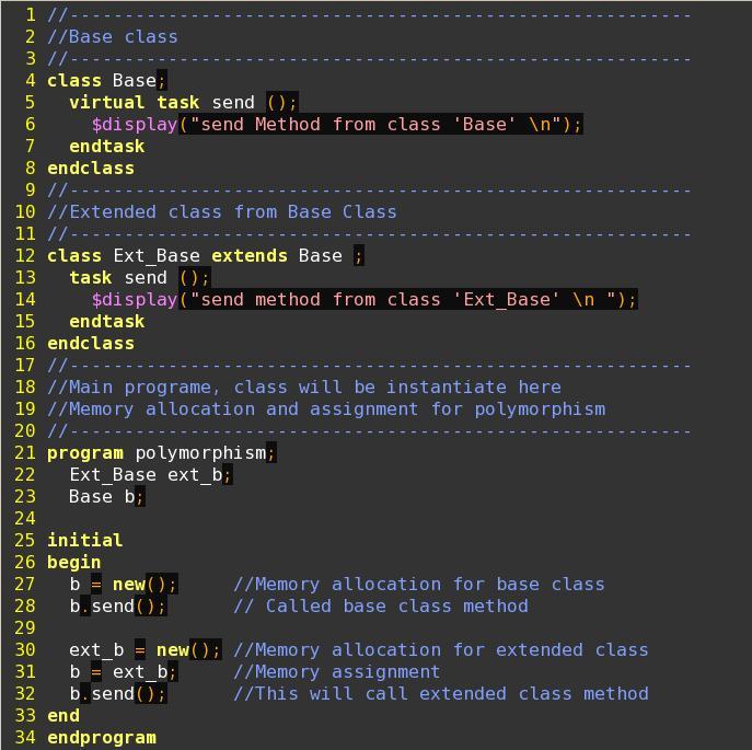
Let me give you a brief example to understand polymorphism in detail which helps you in your test bench development:

Example:


Note: Click on the image to see example with big fonts

When you run above example you will see below result:

Output :
send Method from class 'Base'
send method from class 'Ext_Base'

You will see in example line number 30 where Extended class from base class 'ext_b' has been allocated a memory by doing new and then on line number 31 we assigned a memory between two objects (b and ext_b). Now when we called b.send(), it will call extended class method. This is called polymorphism.

Hope this example, with explanation gives you a better idea on polymorphism. I am sure this will helps you in your test bench development.

Enjoy !
ASIC With Ankit

Is VHDL is gearing up with new methodology called OS VVM??

Dear Readers,

Recently Aldec, Inc has announced in collaboration with SynthWork Design, Inc on Open Source VHDL Verification Methodology (OS-VVM) !! Isn't it interesting !!!

From last couple of years experts have been coming up with lots of new methodology, I have heared about RVM, VMM, OVM, UVM, AVM now its VVM.....!!!!

The way methodology are coming up in market, it indirectly forcing engineers to get ready themselves with up to date with new methodologies !! Companies might accept any available methodology based on their need and other so many factors !! Having knowledge of such methodology definitely helps individuals to jump in to any time !!

Now coming back to VHDL methodology, it seems companies are trying to keep alive the VHDL world !! From last couple of years it has been noted that new language standards such as System Verilog, System C has captured market so quickly and leaving VHDL Designers with dilemma of learning a new languages !!

It seems VHDL methodology is a try to keep alive VHDL world and engineers ! This may open a hope for VHDL Engineers for upcoming new opportunities with VHDL. Now that it is an announcement of openly available methodology, let's see how it goes and how it get success to capture market or companies confidence !!

I haven't started reading these methodology but I am damn sure System Verilog with its methodology would be definitely better than this one at least for verification !! Still I would love to read VVM for VHDL to understand what are the new features they have added for users !!

They said, VVM provides access to advance randomization and functional-coverage capabilities that can be used in any test bench !! I am eagerly waiting to read this methodology to know how they are providing these features with VHDL !!

Don't you think its interesting !!

Enjoy,
ASIC With Ankit

SVA Based Verification

Dear Readers,

In year of 2002, this was called as OVA (Open Vera Assertions). Later on Synopsys Inc had donated the Open VERA language to the Accellera committee to be part of System Verilog language. Several other companies made contributions for the formation of the new Systerm Verolog language. System Verilog language included the assertion language as part of the standard which is called as a “System Verilog Assertions” (SVA).

For verification engineers, main objective is “to verify the design under test (DUT)” thoroughly and make sure there are no functional bugs.

I have seen different approaches to develop test bench:
  1. Directed way of writing a test bench
  2. Constrained random test bench
  3. Semi randomize way of writing test bench

Main points while architecting any verification environments are given below:
- Simulation Generation
- Protocol Checking
- Data Checking
- Protocol Coverage
- Test Plan Coverage

If you see the history and figure it out, you could see, most of the Test benches which were developed before SVA were taking care of all above given categories. Later on when SVA introduced in System Verilog language and two categories, first Protocol Checking, second Protocol Coverage addressed by SVA. These two categories are closer to the design signals and can be managed more efficiently within SVA than by the testbench.

By connecting these assertions directly to the design, the performance of the simulation environment increases tremendously as does the productivity. Using this approach we can share information dynamically during the simulation.
We can not say that without SVA protocol and test plan coverage is not doable. People were doing those things when SVA was not invented!! I can say those parts are easy and effective using the SVA because of its strong constructs and features. For more details on coverage model and brief on Assertion please refer http://asicwithankit.blogspot.com/2011/01/coverage-model-in-system-verilog-test.html

References : A practical guide for system Verilog assertions, By Srikanth Vijayaraghavan, Meyyappan Ramanathan

Enjoy!
ASIC With Ankit

Ohh God ! Would this triggers a ‘Recession Blast 2011-12'?

Dear Reader's

Many of you might be knowing the recent hot news..... Any way let me give you a brief on it. "Recently John Chambers a CEO of CISCO has announce that they are going to fire 10,000 people from his organization from which thousands of them were expected to be gone at the end of August and rest of them would accept the buyouts". Isn’t it a shocking news?


I was shocked after hearing this news and end up with a deep though that “Would this action leads the industry towards the Recession?” We just came out from the global recession. We know that it went so bad that most of the people in this industry were affected one way or other way.

If we go and see the history of CISCO, we can easily see the growth and revenue of organization. Since talking over as CEO of Cisco in 1995, Chambers has grown the company’s revenue from $1 billion to more than $40 billion which shows his capabilities and business quality.

To me, revenue growth would not create the shareholder’s value. Anyone can ‘grow revenue’, especially through acquisitions. All you have to do to grow revenue is buy companies. Important part to create stakeholder’s value is ‘Grow earning per share’. If such kind of action would be taken by few giant companies, then surely our industry will be in crunch!

At the same time I was wondering when I saw few opening on Cisco’s career site. I was just wondering, at one side management is announcing firing and at the same time we can see hiring on its web page! It seems there is nothing to do with industries bad time. It just that organization might have taken some bad decision in past. So I don’t see any problem with current Industry.

If you see recent ASIC industry growth, engineers’ engagements with their clients, and consumer demands, I could see no problem for at least next two years. As we know electronics consumer demands are high now a days, companies has enough work and projections for at least next few years.

I would say this action would not lead this industry towards the Recession! what do you say ?

Enjoy,
ASIC With Ankit

Modelsim Vs Questa Features

Dear ASIC Readers,

We as an ASIC Engineer are frequently using different simulators for our simulation activity. At present time we are frequently using modelsim/Questa and vcs. These are the industry popular and well proven simulators.

I have seen people who are using modelsim / Questa simulator from Mentors but dont really know the exact difference between them.

I have captured some difference between Questa and Modelsim. Though both are simulators from the Mentor Graphics there are some differences between them

Below are the differences I captured :

ModelSim is Mentor Graphics HDL simulator. Questa is Mentor Graphics advanced verification platform that uses ModelSim as its core simulation engine.

Features of the two tools can be grouped into five categories and compared as follows:

1. Language Support
- ModelSim supports SystemVerilog IEEE 1800 for Design only, as well as VHDL (1987, 1993, 2002), Verilog (1995, 2001, 2005), as well as options for mixed language and language neutral licensing and support for SystemC 2.2 IEEE 1666/OSCI 2.2.
- Questa supports all of this as well as SystemVerilog IEEE 1800 for Verification, mixed language licensing (Questa is by default language neutral), PSL IEEE 1850, and SystemC 2.2 IEEE 1666/OSCI 2.2 as standard features.

2. Simulation
- ModelSim supports a single-kernel simulation engine, Verilog RTL & gate level performance optimizations, VHDL RTL & VITAL performance optimizations, performance and memory profiler, separate elaboration, waveform management tool set, VCD and extended VCD support, VCD re-simulation, batch mode simulation, integrated simulation, checkpoint & restore,

- Questa’s simulation support is identical to ModelSim’s

3. Design Entry, Debug, and Analysis
- ModelSim supports an HDL editor, integrated project manager, source code templates and wizards, interactive and post-simulation debug, dataflow graphical and textual causality traceback, source annotation, memory window, extra standalone viewer, multiple waveform windows, waveform compare, C Debugger and transaction viewing for SystemC.

- Questa supports all of this and the C debugger and transaction viewing for SystemC and SystemVerilog are standard parts of the product.

4. Advanced Verification Methods
- ModelSim does not support any advanced verification features.
- Questa supports assertion-based verification (including a library of pre-written assertions called Questa Verification Library or QVL, and an assertion thread debugger), automated test stimulus generation via a constraint solver engine, and PowerAware RTL verification supporting both CPF and UPF formats.

5 Verification Management and Coverage
- ModelSim supports Code Coverage (it is included in ModelSim SE, and an option to other versions of ModelSim).

-Questa supports code coverage along with functional coverage, a unified coverage database (UCDB), coverage viewing, test ranking, and test plan tracking

Hope you find this information useful.

Enjoy reading...!
ASIC With Ankit